architecture
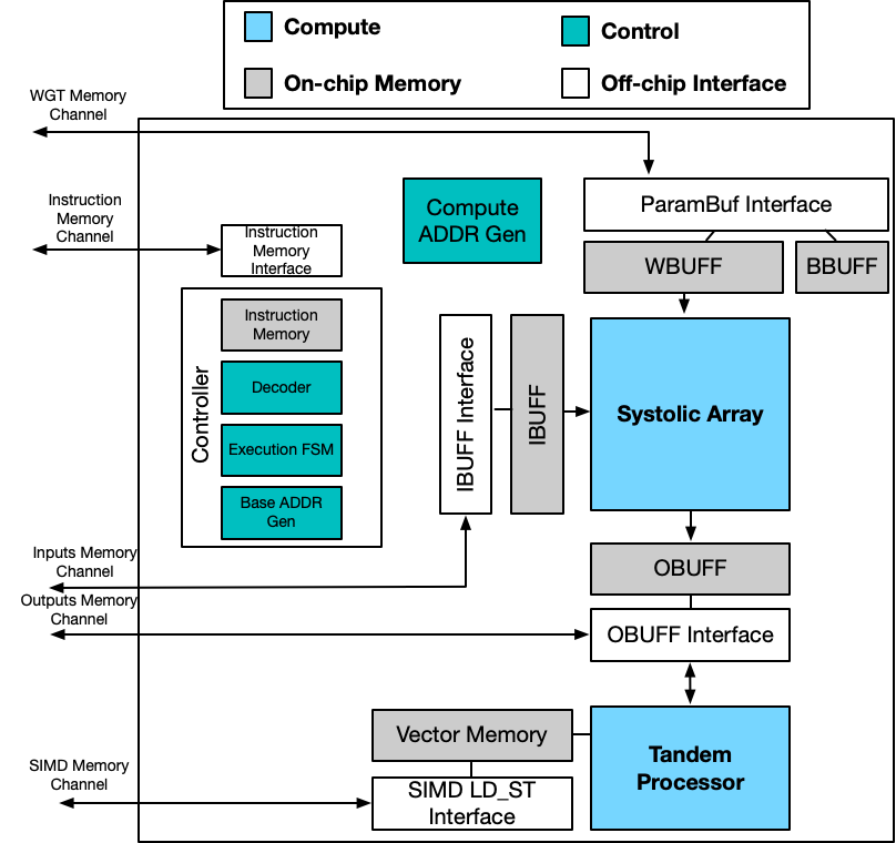
The overall system consists of two core components: a systolic array and a Tandem Processor. Data is supplied to the two engines through the input buffer (IBUF), output buffer (OBUF), instruction memory (IMEM), weight buffer (WBUF), bias buffer (BBUF) and vector memory (VMEM). These interfaces harbor programmable data access modules and controller FSMs that together issue the addresses and requests to load or store a tile of data from/to off-chip memory. The data access creates strided patterns that access the off-chip memory to read/write the corresponding data from/to on-chip buffers and populate the on-chip memory. These interfaces also include tag logic that is in charge of handling double-buffered data transfer to hide the latencies of load/store operations and also facilitate prefetching. Among these interfaces, the interfaces for the OBUF and Tandem Processor handle both load and store operations, while the other interfaces handle only load operations. These interfaces are fully programmable through the instruction set architecture (ISA) of the Tandem Processor. The overall system view is shown below.

Systolic Array
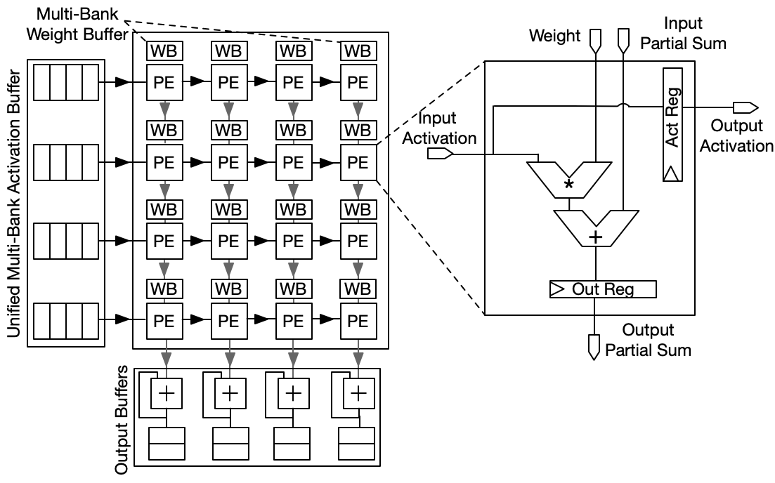
We implemented an systolic array to handle GEMM operations. The systolic array has been the de facto standard architecture for GEMM operation in both academia and industry. A systoic array consists of a 2D array of Processing Elements (PE) to perform matrix multiplications and convolution. Input activations are stored on-chip in the IBUFF implemented as a multi-bank scratchpad, where each bank is shared across PEs within a row. Each PE contains its own bank of WBUFF where the weights are stored. Consequently, at each cycle, an input activation is read from an IBUFF’s Bank and is reused for all the PEs (MAC units) within the row. At each cycle, each PE forwards the input activation to the PE to its right (horizontal) and the output partial sum to the PE to its bottom (vertical). Finally, the outputs are stored in OBUFF which is a shared sctrachpad that Tandem processor can also access.

Tandem Processor
The design of Tandem Processor aims to achieve the following goals. 1) In-tandem execution of GEMMs and non-GEMMs. 2) Balanced efficiency and programmability for the non-GEMM unit. 3) Orchestrating the execution across non-GEMM and GEMM units.
It achieves these goal by the following microarchitecture designs.

On-Chip Memory Organization
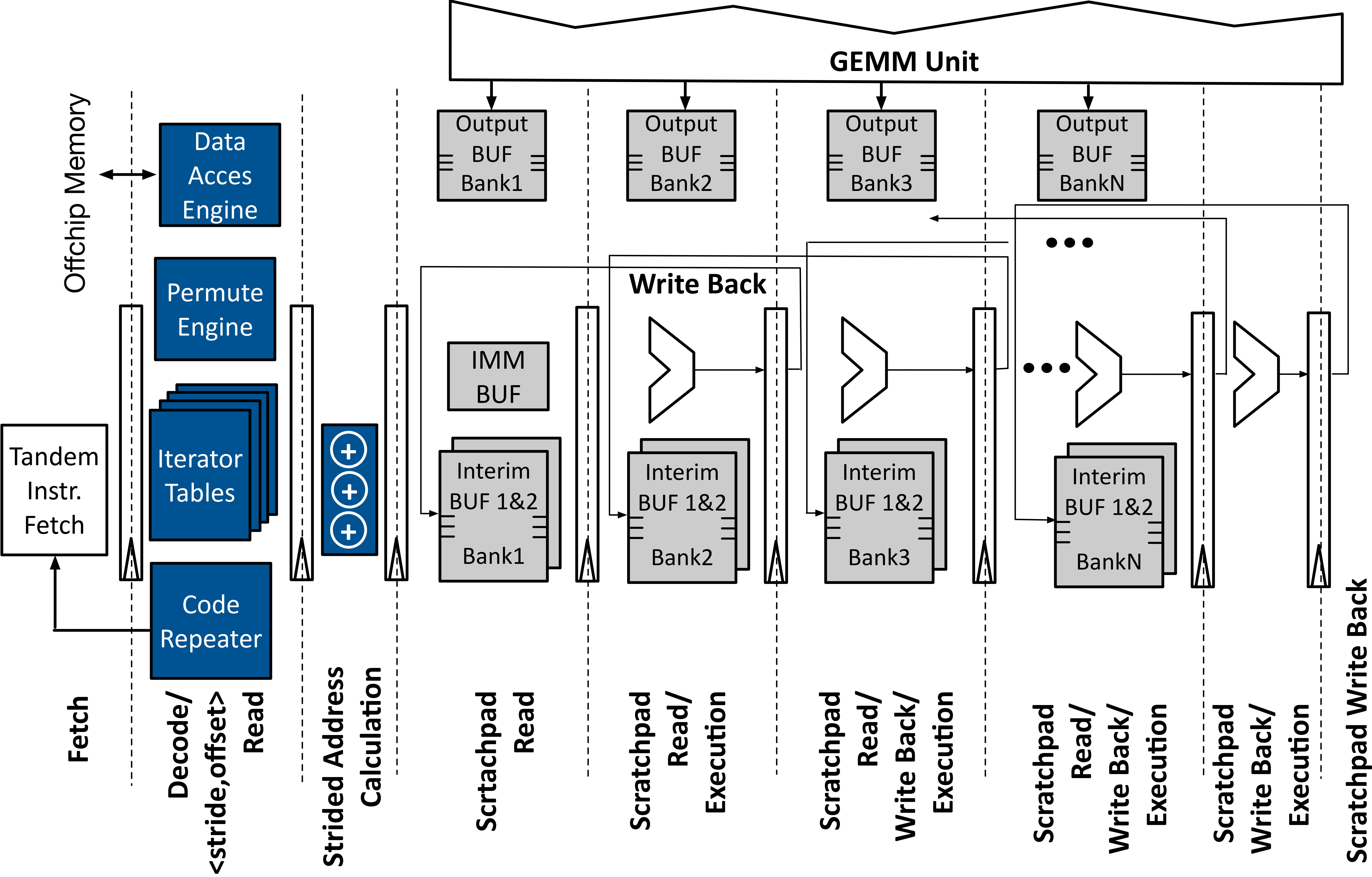
Tandem Processor replaces the entire vector register file and cache hierarchy with a collection of single-level software-managed on-chip scratchpads. Tandem Processor directly accesses and operates on these scratchpads while performing the non-GEMM operations. This design innovation is in contrast to all prior SIMD designs that rely on register file execution and memory semantics. We refer to Tandem Processor scratchpads as Namespaces, Interim BUF 1&2 namespaces represent the central Tandem Processor’s on-chip scratchpads that operate as a storage medium for tensor operands as well as their intermediate results. These scratchpads, which bridge the off-chip memory and Tandem Processor, are populated/drained by a Data Access Engine at a tile granularity. The Tandem Processor compiler configures the Data Access Engine by setting the base address of the off-chip source along with a series of stride values. Note that, the tiled data may be even dispersed across non-contiguous regions of memory lines, yet statically arranged in strided patterns. IMM BUF namespace serves as a small 32-slot scratchpad for immediate values in non-GEMM operations. This buffer is programmed with a series of customized instructions at the onset of non-GEMM layer execution. The last namespace is Output BUF, which serves as the GEMM Unit’s buffer for output values.
Specialized On-Chip Data Access
on-chip address calculations require excessive number of arithmetic instructions which impose runtime overheads. To tackle this challenge, we devise a dedicated pipeline stage for address calculation at the front-end, relieving the burden of address calculation from compute units. We place the Iterator Tables that are used to store the offset and stride information for scratchpad accesses at the decode stage of the Tandem Processor pipeline. There is a dedicated Iterator Table for each namespaces of the Tandem Processor. Upon decoding one arithmetic/logic instruction, the ⟨Namespace ID, Iterator Index⟩ retrieves the address calculation information from the corresponding Iterator Table. The resulting outputs of accessing the Iterator Tables is a triplet address, two for source operands and one for destination operand. Each element of the triplet is a tuple of ⟨offset, stride⟩, indicating that target data resides in Scratchpad[offset + stride]. The triplet address is passed down to the subsequent pipeline stage (Strided Address Calculation) that repetitively assembles a series of scratchpad addresses, each as the result of offset + stride computation. The scratchpad indices propagate down the multi-staged execution pipeline to fetch the tiled operands, perform the non-GEMM operations, and write back the resulting data to the pipeline back-end.
Nested Loop Support
Non-GEMM layers are formed of nested loops of primitive operations with pre-determined iteration counts. Tandem Processor uses software-managed tables in the fetch pipeline stage to orchestrate the execution of nested loop constructs in hardware. Prior to execution, these tables are configured once with the iteration counts and corresponding number of nested loop levels. Once configured, these specialized tables are used repeatedly in conjunction with the iterator tables to execute the loop body. This is crucial, since appropriate ⟨Offset, Stride⟩ tuples need to be employed at each level of loop nest to correctly calculate the scratchpad addresses. This specialized loop execution is unique to Tandem Processor, as prior work [89, 90 ] leveraged hardware-managed loop logic with register-file based designs and did not offer mechanisms to combine it with address calculation.
Arithmetic Logic Units Design
To support a diverse set of non-GEMM layers, We instead leverage the feasibility of implementing complex non-GEMM layers with a set of simple primitive operations. For instance, GeLU operator can be implemented using five multiplications, three additions, a sign, an absolute, and a minimum operations. We consider a union set of these primitives that is comprehensive enough to support a wide range of non-GEMM layers.
Tandem Processor Coordination, Synchronization, and Overall Execution Flow
We use tile (sub-tensor) granularity for software pipelining to facilitate execution overlap between GEMM and non-GEMM units. To enable tile-based coordination, enable a fluid ownership of the GEMM unit’s Output BUF for Tandem Processor, obviating redundant data communications. After the GEMM unit completes storing the intermediate data in the Output BUF, Tandem Processor takes the ownership of the buffer and directly executes its computations on the stored data. We leverage the compiler to weave a set of synchronization instructions between GEMM and non-GEMM instructions. These synchronization instructions realize the following objectives: (1) They identify the code regions for GEMM unit and Tandem Processor, facilitating the instruction dispatch. (2) They define the flow of execution between GEMM and non-GEMM units. (3) They govern the handshaking mechanism between the acceleration units.
ISA
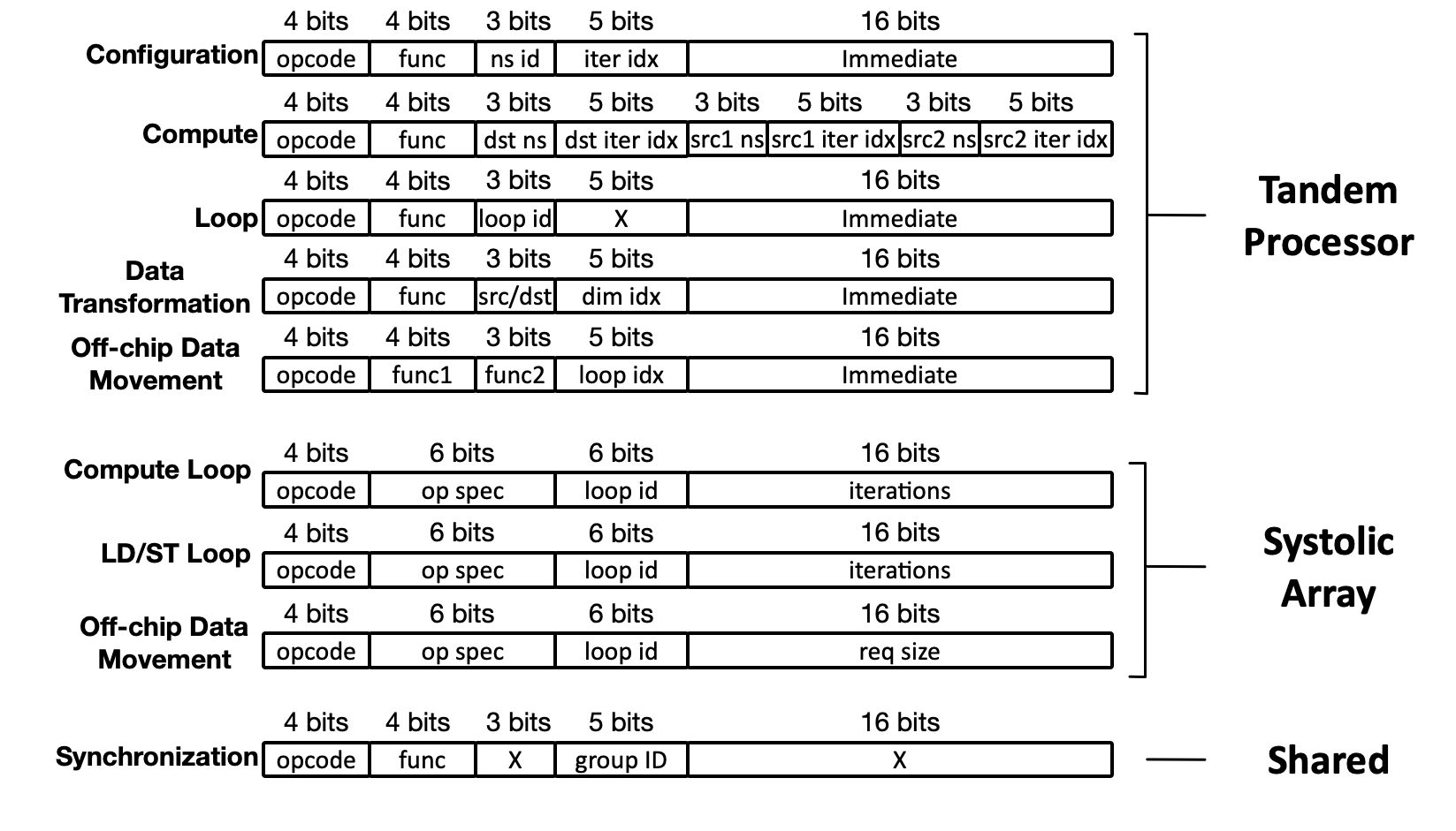
Tandem Prcoessor and systolic array are fully programmable through the ISA available here. The ISA is consist of the serval class which is discribed in detail below.

Tandem Processor ISA
Configuration Instructions
This class includes two opcodes. The ITERATOR_CONFIG opcode is used with three functions (func bits): (1) BASE_ADDR to fill the Iterator Tables with the base addresses for the scratchpads, (2) STRIDE to fill the Iterator Tables with strides for the scratchpad address calculation, and (3) IMM BUF to fill the immediate buffer with the immediate values needed for non-GEMM operations. The ns id and iter idx fields identify the target namespace and the index to its corresponding Iterator Table. Also, this instruction is used to set the immediate values in IMM BUF. Another opcode is DATATYPE_CONFIG, which is used for datatype casting.
Compute Instructions
Opcode ALU is defined with various func bits to support Add, Sub, Mul, MACC, Div, Max, Min, Shift, Not, AND, OR operations on src1 and/or src2 operands. Additionally, this opcode supports MOVE/COND_MOVE instructions for scatter/gather operations. Opcode CALCULUS consists of mathematical operations such as absolute value and sign. Opcode COMPARISON supports logical comparisons. The operands (src1/src2/dst) for each instruction are specified by using a 3-bit ns id to locate the buffer, and a 5-bit iter idx corresponding to the stride and offset.
Loop Instructions
This class is used with the LOOP opcode to configure the Code Repeater. This opcode is used with SET_ITER function bits to specify the iterations for each loop identified by loop id. The SET_NUM_INST function is used to identify the number of instructions in the loop body. To cope with the customized on-chip memory accesses for each loop dimension, the SET_INDEX function is used, while the rest of the instruction bits are used to set the associated ⟨ns ID, iter idx⟩ for the three operands (similar to compute instructions). The loop instructions are designed to support arbitrary levels of nesting (up to eight, each of which is identified by loop id field) needed by non-GEMM operators.
Data Transformation Instructions
This class is used with two opcodes: (1) PERMUTE for permuting multi-dimensional tensors using the Permute Engine. (2) DATATYPE_CAST for datatype casting. For PERMUTE opcode, SET_BASE_ADDR, SET_LOOP_ITER, and SET_LOOP_STRIDE functions configure the base addresses, shapes, and strides, respectively, for both the source and destination’s tensor dimensions (identified by dim idx). Then, with the START function, the iterators start generating the address for the source and destination according to the desired permutation. Additionally, the LSB bit of the Immediate field while using the START function identifies if this permutation operation requires shuffling the data across the SIMD lanes/scratchpad banks or not. DATATYPE_CAST opcode is used to cast tensor elements to various fixed-point representations such as FXP32, FXP16, FXP8, and FXP4 needed by the GEMM unit.
Off-Chip Data Movement Instructions
TILE_LD_ST opcode describes the data tile transfer between off-chip memory and Interim BUFs. The func1 field includes various fucntions: The LD/ST_CONFIG_BASE_ADDR function is used to generate the base addresses of each tile, then the shape and strides are configured using the LD/ST_CONFIG_BASE_LOOP_ITER/STRIDE functions. Also, LD/ST_CONFIG_TILE_LOOP_ITER/STRIDE functions are used to configure the Data Access Engine to generate the addresses required for each tile. Finally, LD/ST_START function triggers the Data Access Engine to start populating/draining the intermediate buffers. The func2 field is used to identify the target buffer between Interim BUF 1&2.
Systolic Array ISA
Compute Loop Instructions and LD/ST Loop Instructions
This class is used with the SA_LOOP opcode to configure the Code Repeater on the systolic array. It consists of xx opcodes. SA_LOOP specifies the iterations for each loop identified by loop id. SET_LOOP_STRIDE and SET_LOOP_ADDR works together to set the the base addresses for the scratchpads and STRIDE to fill the Iterator Tables with strides for the scratchpad address calculation. The mechnism is identical to the Tandem Processor Configrueation and Loop instruction. The LD/ST Loop instruction shares the same LOOP structure with the compute loop.
Off-Chip Data Movement Instructions
LD_ST insturction specify the request size of each LD/ST instruction. The LD/ST Loop instruction shares the same LOOP iteration structure with the compute loop.
Shared Instructions
Synchronization Instructions
The func bits are defined as ⟨GEMM/SIMD,START/END,EXEC/BUF,X⟩. The START/END along with EXEC bit identifies the regions of instructions that belong to Tandem Processor and GEMM Unit (identified with GEMM/SIMD bit accordingly), which helps dispatch instructions to the appropriate unit. Also, this instruction can be used with EXEC bit to notify the GEMM Unit that the execution of non-GEMM operations of the running tile is completed, or with BUF bit to notify GEMM Unit that the OUTPUT BUF is released and ready for the subsequent tile.